To ensure that a part ultimately meets the requirements, the foundation for it must be laid right at the beginning. An error-free technical drawing is therefore crucial. In this blog post you will learn what it takes to do so.
To specify the shape, form, orientation and location of features on a part, form and position tolerances are used. These tolerances reflect the actual relationship between mating parts. It is therefore crucial to create drawings with properly applied geometric tolerances because they provide the best opportunity for uniform interpretation and cost-effective assembly.

Generally, a distinction is made between two different tolerances: position tolerances and form tolerances. They serve to define the «ideal shape» of a component. Since the manufactured piece can deviate from this «ideal shape» for various reasons, the designer defines such tolerances in his drawings. These should be chosen in a way that the production remains cost-effective on the one hand, and on the other hand the component can fulfil its tasks completely despite the small deviations.
Form tolerances
All form tolerances apply to single or individual features. Consequently, form tolerances are independent of all other features. Thus, no datums apply to form tolerances. The form tolerances must always be indicated exactly on the drawing. Each form tolerance has its own symbol. The form tolerances include: Straightness, Flatness, Circularity, Cylindricity, Profile of a line and Profile of a surface
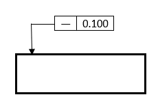
Let’s take a look at an example for form tolerances: Straightness is a condition where a line element on a surface, a median plane is a straight line. The line element must lie between two parallel lines to fulfill the straightness tolerance. The distance between the parallel lines is the straightness tolerance. The symbol for straightness is «―» as shown in the picture below.
Position tolerances
In the production process position deviations are to be expected. Therefore, you should take them into account when creating the drawing. This is what position tolerances are for. Contrary to form tolerances, position tolerances are referred tolerances and thus always refer to a datum. Each position tolerance has its own symbol. The position tolerances include: parallelism, perpendicularity, angularity, position, concentricity, symmetry, runout.
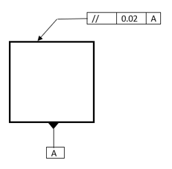
Let’s take a look at an example for position tolerance: Parallelism is the condition of a surface or center plane, located at the same distance to all points from a datum plane. Also, parallelism is the condition of an axis, equidistant along its length from one or more datum planes or a datum axis. The symbol for parallelism is «//» as shown in the picture below.
How to create a technical drawing
The following provides a guideline for creating technical drawings and explains what needs to be considered when creating drawings.
- First, you need to chose the right sheet size and accordingly the appropriate drawing scale. When choosing, it is important that the drawing object can be displayed and dimensioned with all its details when creating the drawing. For larger workpieces, you can either take a larger sheet size, for example A0, or you need to choose an appropriate drawing scale.
- Label the drawing sheet. After choosing the appropriate format for the technical drawing, the title block of the drawing sheet should be correctly labelled right at the beginning. For this purpose, the designation of the component, the name of the creator, the scale and the material are entered in the title block before the drawing is created.
- Choosing the right position. Should a front view be displayed, or do you want to create a side view or a top view? The choice of the appropriate view depends on the projection or axonometry under which the drawing object can be clearly represented.
- Drawing. If you decide to create a technical drawing, you should start by sketching the outlines of the component in the various views. Subsequently, the centre lines and the edges of the workpiece are inserted into the technical drawing. After completing the technical drawing, superfluous auxiliary lines can be removed.
- Labelling and dimensioning the technical drawing. After the technical drawing has been created, further information can be added. This includes information such as dimensions, tolerances, surface finishes and anything else that the draughtsman deems important.
For further information about machining, download now our «Guidelines for machining with copper based alloys»